
- 21 June, 2016


DB-Engines article – Enriching Property Graphs with Relationship Objects
A Classic Property Graph Scenario
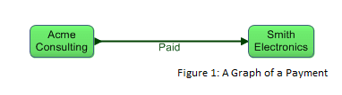
Suppose we are creating a large graph database that contains information about payments between companies. A graph database analyst might start off modeling the payments as shown in Figure 1, which expresses who paid whom. (All graph figures in this article were produced using Gruff, a tool for visualizing graph databases, operating over the AllegroGraph graph database system.)
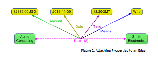
This seems straightforward enough. Now suppose that we want to record more information about payments, such as the amount of the payment, the means of payment (direct debit, e-check, wire, etc.), the date and time when the payment occurred, and so forth. A traditional property graph approach places these properties on the edge that connects the payor and payee nodes, as shown in Figure 2.
Optimizing Visualization
This technique of loading up a graph’s edges with properties is certainly useful, but it has some notable limitations at large scale. When a payments analyst wishes to explore the graph with visual graph display tools, it becomes onerous to visually navigate a graph with many payments due to the clutter that large numbers of property values produce.
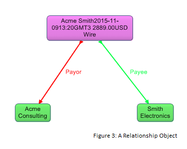
Such difficulty is one reason for refactoring the edge between the payor and payee into a node that we call a relationship object. In Figure 3, the payment relationship object serves as a visualization refinement, as it displays multiple property values in one node, via a label for the node that summarizes the values. Experience has shown that analysts who visually navigate graph databases find the relationship objects pattern provides substantial relief from the otherwise cluttered display.
Addressing Search Issues
At this point, however, the reader might be wondering whether, in providing this optimization for visualization, we have sacrificed ease and efficiency of conducting searches. Such concern is justified; eliminating the individual property representations and the payment edge that directly connects the payor and payee makes queries more convoluted and carries a performance penalty. To address this issue, there are two additional aspects to the relationship objects pattern: preserving individual properties and constructing a super graph.
Preserving Individual Properties
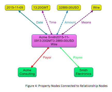
Typically when we use the relationship objects pattern we also model each of the individual properties of the relationship, and we attach the property values directly to the relationship object (see Figure 4). If the individual property values were not in the graph, it would be awkward to search for payments by their properties using query languages such as SPARQL; we would have to search through the display label of the relationship node, which would be a suboptimal way to query.
Note, though, that in most visualization scenarios we omit the individual property representations from the display. Otherwise we would still have the problem of overly cluttered graph displays.
Note also that, since we retain the individual properties in the graph, graph database tools that understand the relationship objects pattern can generate the summary label for the relationship object.
Constructing a Super Graph
The other aspect of the relationship objects pattern that addresses the search issues is that we construct a super graph, which consists of edges that correspond to the relationship objects and link the parties directly.
In Figure 5, the direct edge labeled “Strong Payment Link” is part of the super graph. The edges of the super graph enable us to query for payments via the direct edge without the complication and performance hit of querying over the relationship object and its Payor and Payee properties.
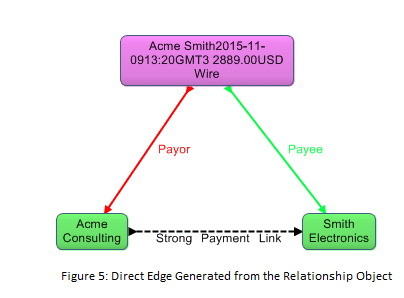
We can define the direct edges of the super graph explicitly as part of the modeling process. However, in many cases it is preferable to generate the direct edges algorithmically to add them to the graph; for instance, for a semantic graph database we can use SPARQL to generate the super graph from the payment relationship objects.
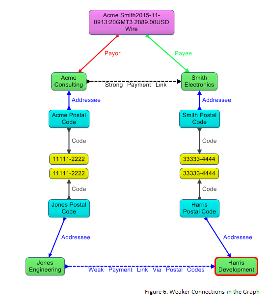
It can also be useful to generate direct edges that connect nodes whose logical connection to each other in the graph database is weaker. Figure 6 depicts a scenario in which the two parties did not pay each other directly, but nevertheless may be connected to the payment indirectly because at the time of the payment they each shared the same nine-digit US postal code with one of the parties to the payment. (This example assumes that full addresses for the parties are not available in the database.)
We call direct edges generated from these weaker connections weak links. By contrast, the generated edge connecting the payor and payee in our example is a strong link because, in the graph from which the edge is generated, the relationship object has already explicitly asserted the logical relationship. The super graph includes both strong and weak links.
As is the case with strong links, in semantic graph databases we can use SPARQL to generate weak links.
Note also that, in cases where a party has made multiple payments to another party, we generate only one strong payment link between the parties. Thus the super graph condenses the data and makes it faster to find direct payment connections between parties. We do the same with weak links.
Applying the Relationship Objects Pattern
Imagine that we are a government agency or financial institution that wants to use the payments graph database to investigate various forms of fraudulent financial activities. We can use the strong links – that is, the direct edges that correspond to the relationship objects – to query our payments graph to reveal payments between two parties, where the payment is direct.
Querying over the “Strong Payment Link” edge would, for instance, identify the Acme-to-Smith payment direct edge of our example. Then we can interactively ask a graph database visualization tool that has the requisite capabilities to show us other nodes connected to Acme Consulting and Smith Electronics, which reveals the relationship object with its detailed data. We call this process of displaying relationship objects after querying the super graph rehydration. In cases where a strong payment link represents multiple payments, rehydration reveals the detailed information about each payment.
Querying over strong links, followed by rehydration, can reveal important information for investigators. However, uncovering fraudulent activities often requires finding connections among companies that fraudsters seek to obscure. By generating weak links and then querying over them, we can detect that certain parties not directly involved with each other in a payment may in fact be involved behind the scenes, and we can flag such payments and parties for possible investigation. The weak payment link of our example, derived from the co-occurrence of postal codes, would not in itself be sufficient to warrant an investigation of the payment, but may be one part of a puzzle that investigators piece together, using additional weak and strong links.
More Reasons for Using Relationship Objects
Thus far we have focused on the need to optimize visualization as a rationale for using relationship objects. However, there are additional reasons to employ them.
Complex Relationship Properties
In conventional property graphs, properties attached to edges can only be of simple scalar data types, such as string, integer, date, and so on, which is a problem if the property itself is complex.
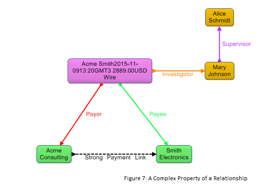
For instance, what if whenever we flag a payment as suspicious we assign an investigator to it? Assume that we model that as an investigator property of the payment. If we want the value of that property to be more than a string such as “Mary Jones” – that is if we want the value to be a first class Mary Johnson node that could have its own properties and participate in other relationships – a conventional property graph would hit a wall. But if the payment is modeled as a relationship object, which is a first class node in its own right, then this is no problem.
Figure 7 shows the scenario where a first class Mary Johnson node participates in the Supervisor relationship. (Note that the Investigator property could be added to the label for the Payment relationship object, and the Supervisor relationship could be refactored into a relationship object.)
N-Ary Relationships
Suppose that we wanted to model a joint venture in which two companies invest in a third company. A conventional property graph as in Figure 8 is insufficiently expressive to model the venture properly, because it does not capture the fact that the two investments are part of a joint effort, and the graph cannot define properties of the venture itself. The joint venture relationship object in Figure 9 addresses this limitation.
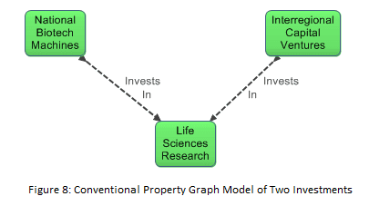
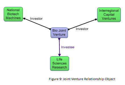
The joint venture scenario is a case where, regardless of visualization factors, a relationship object is required to express what needs to be expressed. The limitation of the conventional property graph of Figure 8 is that it only models two disconnected binary relationships. The joint venture is by nature what some modelers call an n-ary relationship, signifying that it is a relationship among more than two things. In general, n-ary relationships have to be modeled as relationship objects.
Conclusion
In some cases relationship objects are mandatory to logically model the scenario at hand, but even in cases where they are not necessary from a logical standpoint they are very useful to optimize the visual display of complex relationships. Relationship objects make it far more straightforward to interactively explore large graph spaces in an aesthetically pleasing and effective way using advanced graph visualization tools.
At the same time, relationship objects do not sacrifice efficiency of search, because the super graph that we generate provides direct connections between the parties to a relationship so that even in graphs with large branching factors we still can perform very fast search.
There are many additional applications of relationship objects in finance, biotech, medicine, transportation, and more. Whenever graph databases rise to an industrial scale, the relationships objects pattern is found to be useful.
About the Author: Jans Aasman is Ph.D. psychologist and expert in the Cognitive Science – as well as CEO of Franz.com, an early innovator in Artificial Intelligence and provider of Semantic Graph Databases and Analytics. As both a scientist and CEO, Dr. Aasman continues to break ground in the areas of Artificial Intelligence and Semantic Databases as he works hand-in-hand with organizations such as Montefiore Medical Center, Blue Cross/Blue Shield, Siemens, Merck, Pfizer, Wells Fargo, BAE Systems as well as US and Foreign governments.
Dr. Aasman is a frequent speaker within the Semantic technology industry and has authored multiple research papers, bylines and is one of 15 CEOs interviewed in a new book, “Startup Best Practices”.
Dr. Aasman spent a large part of his professional life in telecommunications research, specializing in applied Artificial Intelligence projects and intelligent user interfaces. He gathered patents in the areas of speech technology, multimodal user interaction, recommendation engines while developing precursor technology for the iPad and Siri from 1995 to 2004. He was also a part-time professor in the Industrial Design department of the Technical University of Delft.
Related articles

AllegroGraph Named “2025 Best Knowledge Graph” by KMWorld Readers’ Choice
- By Franz Inc.
- November 12, 2025

The rise of accountable AI agents: How knowledge graphs solve the autonomy problem
- By Franz Inc.
- October 30, 2025